

『Bidirectional electromagnetic flowmeter』Related information(v cone flow meter|rotary gas meter|gallon meter|gear meter|metal tube rotameter|glass tube rotameter|nutating disk meter|transit time ultrasonic flow meter|wedge flow meter|pd meters|hydraulic flow meter|ultrasonic water flow meter|water flow meter|air flow meter|magnetic water flow meter|oxygen flow meter|gas flow meter|argon flow meter|air velocity meter|gasoline flow meter|fuel flow meter|ultrasonic water meter|digital water meter|nitrogen flow meter|solid flow meter|Oxygen tank flow meter|digital water flow meter|diesel fuel flow meter|steam flow meter|02 flow meter|compressed air flow meter|oil flow meter|liquid flow meter)

1. Working principle of electromagnetic flowmeter
The working principle of electromagnetic flowmeter is based on Faradays law of electromagnetic induction, and its core is to calculate the flow rate by measuring the induced electromotive force generated by the movement of conductive fluid in a magnetic field. The following is the specific principle and characteristic analysis:
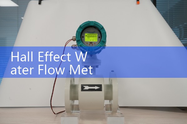
First, the core working principle is that when a conductive body flows through the measuring tube of an electromagnetic flowmeter at an average flow velocity v, a constant magnetic field (magnetic flux density B) perpendicular to the fluid direction is applied inside the measuring tube. According to Faradays law, positive and negative ions in a fluid undergo deflection under the action of Lorentz force, forming an induced electromotive force E between the electrodes on both sides of the measuring tube that is proportional to the fluid flow velocity. Its mathematical expression is: E=K × B × D × vE: Induced electromotive force (unit: Hertz volts, V) K: Instrument constant (related to structural parameters such as electrode shape and magnetic field distribution) B: Magnetic flux density (unit: Tesla, T) D: Inner diameter of the measuring tube (unit: meter, m) v: Average flow velocity of the fluid in the axial direction of the electrode section (unit: meter/second, m/s). By measuring the electromotive force E and combining known B, D, and K, the volumetric flow rate Q (Q) of the fluid can be calculated.=π D2v/4). Figure: Schematic diagram of the structure of an electromagnetic flowmeter (magnetic field direction perpendicular to the paper, fluid flows from left to right, electrodes are located on both sides of the measuring tube). Str
III. Typical Application Scenarios: Municipal and Environmental Protection, Sewage and Rainwater Discharge Monitoring, Water Reuse System, Flow Measurement, Industrial Process Control, Chemical Industry: Acid and Alkali Solution, Electrolyte Solution Transportation, Food Industry: Juice, Syrup, Alcohol Production Process Mon
 Hot Product
 Related AD